Dave, if you take a look at the curves it should give you an idea of how much difference 20v would make. I'd be tempted to run them a smidge cooler and increase life expectancy.
-- Andrew
Next project?
-
Dave the bass

- Amstrad Tower of Power
- Posts: 12276
- Joined: Tue May 22, 2007 4:36 pm
- Location: NW Kent, Darn Sarf innit.
#197
Hi Andrew, thanks for the advice. Ok, lets take it a bit further. Here's the curves of a 2A3...Andrew wrote:Dave, if you take a look at the curves it should give you an idea of how much difference 20v would make. I'd be tempted to run them a smidge cooler and increase life expectancy.
-- Andrew
You said in the quote above to look at the curves and the difference 20V of HT would make. What am I to look at, sorry if this is a simple question but I'm not 100% sure what I should be looking for.... is it a point where the 300V and 320V vertical axis cross the 60mA horizontal? I know we try and get valves to operate in the linear (straight?) bit of the curve. Thats right isn't it?
DTB
"The fat bourgeois and his doppelganger"
#198
Ok, to do this you need to draw the DC load line for the valve. In the interests of simplicity, lets assume the DC resistance of the output transformer is smal by comparicon with the cathode cap, so the voltage applied to the valve anode stays roughly constant as we change the current,
Lets also assume you have a B+ of 360v, and a 1k cathode resistor.
So if there is no current through the valve, the voltage across the valve will be the entire B+, as there is no current through the cathode resistor, so no voltage drop. So we can draw a point on the graph at 360v 0ma. Now if we assume there is 100ma flowing through the valve, there will be 100v dropped across the cathode resistor, so the remaining voltage on the valve will be 260v, so we can draw a point on the 260v, 100ma point.
Now we casn join those two points up with a line, thats the load line of the 1k cathode resistor.
Now we look at the grid lines. Start with the -60v line. If there is -60v on the grid, the cathode must be at 60v. And as we have a 1k cathode resistor the current through the cathode resistor we know that the current through the valve must be 60ma. So put a dot on teh 60v grid line where it crosses the 60ma line. Repeat for each grid line, 70v crosses 70ma, 50v crosses 50ma and so on.
Now draw a curve through those points.
Where the two lines cross, will be the op point for that valve with a 360v B+, and a 1k cathode resistor. You should see they cross somewhere about 290v 59ma (or so), so now we know the power that will be dissapated at idle, 17.1w
Now if we start with a 20v higher B+, we can draw the same 1k load line, but starting at 380v, it will have the same slope as the other line, but 20v further right. Now when we look where the new line crosses the other curve, we so its something like 310v 60ma and the power now will be 18.6w
You could have just gestimated that the value would change by about that amount, but I thought it would be more fun to do it graphically.
Whenever an honest man discovers that he's mistaken, he will either cease to be mistaken or he will cease to be honest.
-
Dave the bass
- Amstrad Tower of Power
- Posts: 12276
- Joined: Tue May 22, 2007 4:36 pm
- Location: NW Kent, Darn Sarf innit.
-
Dave the bass
- Amstrad Tower of Power
- Posts: 12276
- Joined: Tue May 22, 2007 4:36 pm
- Location: NW Kent, Darn Sarf innit.
#200
Sorry for the delay, the neighbours popped round last night to let us know they're going away for the weekend so I had a full-on listening session until silly o' clock.
Here's an apple for teach...

[/creep mode].
OK, here's my homework (Sir!).
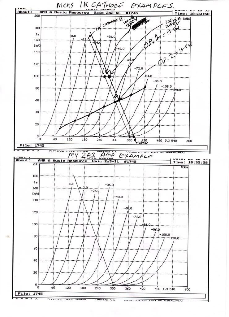
On the bottom graph I'd like to plot the 'real-world' loadline using the 750R 300V B+ I've got at the mo. I know from past measuring I've got approx 60mA current flowing with 250 across anode-cathode, grid is at -45V. That means approx 5V drop across the primary of the o/p TX. I've tried to plot that on the bottom graph. Is that bit right so far?
DTB
Here's an apple for teach...
[/creep mode].
OK, here's my homework (Sir!).
On the bottom graph I'd like to plot the 'real-world' loadline using the 750R 300V B+ I've got at the mo. I know from past measuring I've got approx 60mA current flowing with 250 across anode-cathode, grid is at -45V. That means approx 5V drop across the primary of the o/p TX. I've tried to plot that on the bottom graph. Is that bit right so far?
DTB
"The fat bourgeois and his doppelganger"
#201
Think so, at 60ma if you have 5v across the OP TX, then we can guestimate its DCR as 84R, so you can combine this with the cathode resistor and plot what happens with the valve. At 0ma you have no drop in the anode and cathode load, so 300v, 0ma is one point,
Then at 100ma, you would drop 75v across your cathode resistor, and 8.4v across the TX, so the valve see's 300 - ( 75 + 8.4 ), so thats a point at 217v, 100ma
Just remember for later, that we are looking at the DC conditions here.
Then at 100ma, you would drop 75v across your cathode resistor, and 8.4v across the TX, so the valve see's 300 - ( 75 + 8.4 ), so thats a point at 217v, 100ma
Just remember for later, that we are looking at the DC conditions here.
Whenever an honest man discovers that he's mistaken, he will either cease to be mistaken or he will cease to be honest.
-
Dave the bass
- Amstrad Tower of Power
- Posts: 12276
- Joined: Tue May 22, 2007 4:36 pm
- Location: NW Kent, Darn Sarf innit.
#202
After my recent bout of being an Audio equivalent of Arthur Daley I've finally bought my own 2K5 o/p TX's. (Cue sigh of relief from Nick who's AJ's I've had 'on-test' for approx 19months!).
Here they are in all their Silvery splendidness...
and in situ,
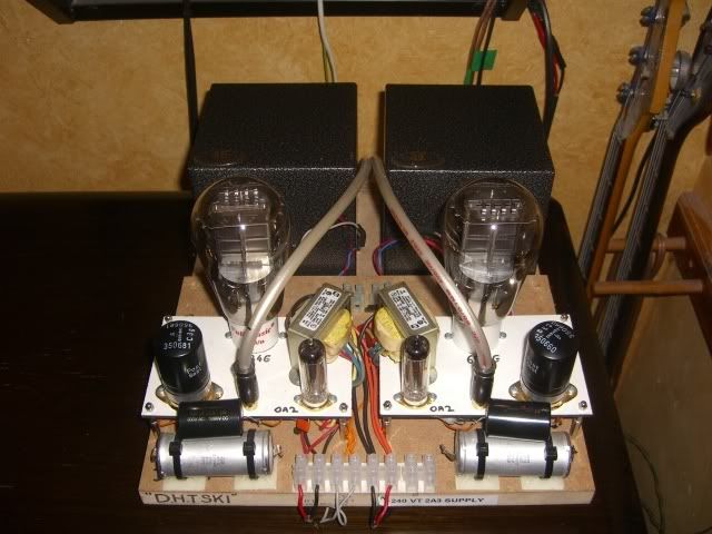
The lovely fella that is AndrewI has also given me gratis (psssst...he's actually loaned them but he might forget..y'know what his memory's like ) a pair of sexy caps to try out in place of the ruskie teflon couplers. I was convinced these were the best thing since sliced bread then A/B'd 'em against the Teffers and wasn't so sure then (after advice) have hard-wired them in and lo and behold I think I'm in love.
I'm developing expensive tastes.
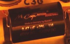
Who'd like to buy my house? I'd like to buy 2 of these caps please!
DTB
Here they are in all their Silvery splendidness...
and in situ,
The lovely fella that is AndrewI has also given me gratis (psssst...he's actually loaned them but he might forget..y'know what his memory's like
I'm developing expensive tastes.
Who'd like to buy my house? I'd like to buy 2 of these caps please!
DTB
"The fat bourgeois and his doppelganger"
-
pre65

- Amstrad Tower of Power
- Posts: 21400
- Joined: Wed Aug 22, 2007 11:13 pm
- Location: North Essex/Suffolk border.
#205
DTB has bought a pair of AEs for himself (as i read the post !)
""After my recent bout of being an Audio equivalent of Arthur Daley I've finally bought my own 2K5 o/p TX's""
""After my recent bout of being an Audio equivalent of Arthur Daley I've finally bought my own 2K5 o/p TX's""
The only thing necessary for the triumph of evil is for good men to do nothing.
Edmund Burke
G-Popz THE easy listening connoisseur. (Philip)
Edmund Burke
G-Popz THE easy listening connoisseur. (Philip)
-
Dave the bass
- Amstrad Tower of Power
- Posts: 12276
- Joined: Tue May 22, 2007 4:36 pm
- Location: NW Kent, Darn Sarf innit.
#206
Ta Simon, well... y'know...all that money I saved while I was busy wearing-out all the flux in Nicks AJ's I managed to save up (and sold lots of things) and thought I might as well go and get summat half reasonable seeing as I'll be playing in 2A3/DHT-land for a while yet. I did have to prise his fingers from the Superglue bond and remove the clamps from Andrews hands to get at themsimon wrote:Very nice OPTs Dave, good choice. Can't believe Andrew has actually parted with them.
So how do they compare with the AJFs???
Sound-wise it's early days yet but on first impressions I'd say they're deffo more brighter in the mids and extend higher than the AJ's. The detailing is simply fabbo. It's funny 'cos it's not as though it's 'trebly' or the like, just more mircoscopic, sorry, I'm not very good at describing stuff that well. Time will tell but I'm happy at the moment Simon.
I've got my own 5K AJ's in 6EM7 and have always been pleased with them, same with Nicks loaned 2K5's, they're very good value I think but then again I've never experienced cheapo Chinese stuff so maybe I'm talking out my bumbum!.
Yep, extravagant I know but I'm super-chuffed so far.Andrew wrote:Did Andrew sell his Silver Amorphous then?
-- Andrew
Pretty much Phil, 2nd-hand Silver Amorphous AE's.pre65 wrote:DTB has bought a pair of AEs for himself (as i read the post !)
I've also treated myself to some Cinemag step up TX's in preparation to return your kindly-loaned Denons back to. I need to house them first and fettle in switchable primary loading first, OK if I hang onto your Denon's until Owston? (I've only had them for how-many years!!!) I'm hoping to have 'em boxed and finished by then.
Then comes a bit more 2A3 fettling, then I've the a TT and arm to sort out then a better phono stage and then some Saburo's to build over Christmas.
S'all go innit!
DTB
"The fat bourgeois and his doppelganger"

-
Dave the bass
- Amstrad Tower of Power
- Posts: 12276
- Joined: Tue May 22, 2007 4:36 pm
- Location: NW Kent, Darn Sarf innit.
#208
Yes of course Ali, I might bring it to Owston.Ali Tait wrote:Dave you lucky boy! Let us know what you think the differences are silver vs. copper when you've had a good listen please.
DTB
"The fat bourgeois and his doppelganger"
-
Dave the bass
- Amstrad Tower of Power
- Posts: 12276
- Joined: Tue May 22, 2007 4:36 pm
- Location: NW Kent, Darn Sarf innit.
#209
So then, I've now got 2 off #83 Mercury Vapour Rectifiers and UX4 sockets.
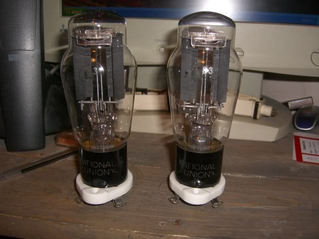
I'd like to use 1 in the PSU of C3g->2A3. The other might go into 6EM7 or I'll keep it for spare.
I just want to check I've got this right.... using these NOS 83's I'd need to power up the 5V heater winding for approx 30 mins on first power up BUT not apply HT at this point. Just get them warmed up. After this initial 'burn in' stage approx 30 secs is OK before HT is applied I've also read.
After they're warmed up is it OK for me just to switch in the HT? Click..just like that on a switch or something? The TX is about 380-0-380. Our Will mentioned a switch in the CT in a previous post, is that the normal way of switching in HT like that or would a time delay relay or such be best. Whats the norm in a situation like this?
This is a first (as ever) for me hence all the questions. I don't want to bugger them up.
Cheerzen,
DTB
"The fat bourgeois and his doppelganger"
#210
Yep, just to try and explain why the first 30min warmup is needed. Its not so obvious with 83s, but when not in use, the mercury condenses on the inside of the glass, incuding the metal parts. If B+ is applied in this state, the liquid mercury could cause a arc over. So by running them for 30min just with the fillament on means the entire valve gets up to temperature and the mercury vaporises. Then when they ar eturned off, the mercury condenses on the cold bits, which will be the envelope and at the bottom of the valve, so there is no liquid left on the electrical parts.
Once this is done, the valve only needs 30sec or so to get the vapour pressure up, then it can be used.
So after the initial 30min use, try and leave them in a upright position to keep the liquid in place.
With 866s its much more obvious whats going on, there is often droplets of mercury on the inside of the glass, and at first turn on, the liquid can be seen vaporising.
Whenever an honest man discovers that he's mistaken, he will either cease to be mistaken or he will cease to be honest.